|
1949 Delco Brakes Service Manual (Courtesy of Pat Gizz) |
|||||
|
DELCO BRAKE SERVICE MANUAL |
|||||
|
|
|||||
 |
 |
 |
 |
||
 |
 |
 |
|||
|
Fig. 7—Styles of Check
Valve
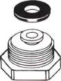
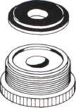
became unseated and interferred
with proper operation of the check valve. The design was changed in
1938 as shown in Figure 8A and this new design has been used on all Master
Cylinders since that time. |
|||||
|
|
|||||
|
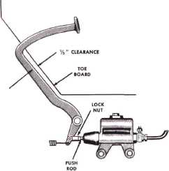
Fig. 6—Pedal Clearance
When the
cylinder is installed on the car, be certain the pedal is adjusted properly to
give approximately 1/2"
clearance from the toe-board (See Figure 6). If the pedal is adjusted
properly, fluid will spurt up
through the port when several quick applications of the brake pedal are
made. Check the stop light
switch with a volt-meter. If defective, replace. Flush the system with
Declene (See Figure 12) and
refill with the recommended Delco Hydraulic Brake
fluid.
Do not fill fluid reservoir
beyond the LOWER end of the Filler Plug. See Figure 2 for recommended
fluid level.
Never reclaim used fluid.
Throw it away.
Increased speeds and the use of
boosters have led to more severe braking operations. Style "A" check
valve, (See Figure 7), where the rubber insert seated itself in the
contour of the check valve was used successfully for many years. In 1942
the "collar button" type, Style "B," was introduced. In this style the rubber insert was buttoned in
place. In 1949, Style "C" was manufactured for the first time. The
rubber insert is firmly held in place by an inner retainer and is entirely
surrounded with perforated metal as
shown in Figure 7.
Until 1938, the head nut and
check valve seat washer shown in Figure 8B were used. There were a few
cases of trouble in the field where the washer |
 |
 |
|||
|
A
ft
Fig. 8—Styles of Headnut
WHEEL CYLINDERS DETAILED
DESCRIPTION AND OPERATION
The Delco Wheel Cylinder (See
Figure 9) is the
unit that changes the hydraulic
pressure produced in the master cylinder into mechanical force
which
is applied to the brake shoes.
The introduction of fluid into the cylinder causes the two pistons to move
in opposite directions thus forcing the shoes into contact with the brake
drum. Pressure cannot be built up in the system until all brake shoes are
in contact with the brake
drums.
WHEEL CYLINDERS DETAILED
SERVICE INSTRUCTIONS
To remove
the front wheel cylinder: —Disconnect
hose from copper tubing at the |
|||||
|
|
|||||
|
6 |
|||||
|
|
|||||