1942 - 1947 CHEVROLET SHOP MANUAL
Section 12 - Electrical System
|
|
|||
|
12-14
|
|||
|
|
|||
|
VOLTAGE SETTING
Stop the engine and remove the regulator cover. The voltage setting of
the regulator is adjusted
|
In case the voltage
does not respond to a slight movement of the spring hanger, the
following adjustments are
necessary:
1. Clean
the regulator points according to instructions given in the repair
section.
2. Adjustment
of the air gap-Push the armature
down all the way by hand. Allow
it to come back up until
points are just closing; then
measure the air gap with a feeler
gauge. The distance
between the armature and the core
should be .075" to .085". The air
gap may be adjusted by
loosening the two upper contact
mounting screws and moving the
upper contact support up or
down as required to secure the
proper air gap, two rights screws
in Fig. 26. Be sure that points are lined up and tighten screws
down well after adjustment.
CLEANING CONTACT POINTS
Cleaning the contact points of the current and
voltage regulator properly is one
of the most important
operations the service man will be called
on to perform. Dirty or oxidized
contact points arc and burn, cause reduced generator output,
and run down batteries. If the
points are properly cleaned
the regulator will be restored to normal
operation. If improperly cleaned,
improvement in performance
will be small and only temporary.
Remove the upper contact support, so that each point may be properly
and separately cleaned. Use a
thin, fine-cut ignition point file and file each point
separately. Do not use the file
excessively on the rounded
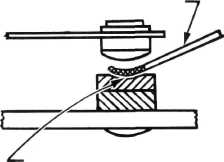
(smaller) point. If a cavity is found in
the flat point, clean it out with
a spoon or riffler file,
Fig. 29. Make sure the cavity is actually
cleaned out, so good, clean
contact is made between the
points. Reassemble contact supports, paying
particular attention to the
position of the insulators, and adjust the air gap.
|
||
 |
|||
|
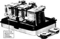
Fig. 28-Voltage Regulator Lower Spring Hangars
by bending the spiral spring hanger down to increase
the spring tension and increase the voltage setting, or by bending the
spring hanger up to decrease
the spring tension and lower the voltage.
Fig. 28. Normally, all adjustments
should be made on one spring and the other spring should not be
touched.
On voltage regulators that are badly out of adjustment
after the points have been cleaned and
the air gap set. it may be
necessary to check the
adjustment of the second spring. To do this, remove
one spring from the regulator; connect the positive lead of the
voltmeter to the generator terminal
of the regulator and the negative lead to a good ground.
Depress the voltage regulator armature
by hand to open the points. Slowly increase the generator speed
until the voltmeter reads approximately
3 volts. Release the armature and
adjust the spring hanger up or
down to secure a voltage
reading of 4.5 to 5 volts. Install the other
spring and complete the adjustment
to 7.2 to 7.4 volts
entirely on this spring, as previously explained,
without again touching the other spring.
NOTE -When the
above adjustments are being made, the unit must be at operating
temperature and the cover must be in place when voltage readings are
taken.
After any adjustments, replace the cover, start
the engine, and set it to run at
a speed equivalent to 30 to
35 miles per hour. Readjust the variable
resistance in the volt ammeter to
obtain a generator output of 8 to 10 amperes. Now check the
regulator voltage, which
should be within the limits given above.
NOTE -Only a slight
bend of the lower spring hanger is necessary to change the voltage
setting.
|
|||
|
RIFFLER FILE
|
|||
 |
|||
|
OXIDIZED CAVITY
EXAGGERATED VIEW
Fig. 29-Cleaning Flat Regulator Point
|
|||
|
|
|||