1942 - 1947 CHEVROLET SHOP MANUAL
Section 3 - Front Suspension, Axle & Springs
|
|
|||
|
3-10 |
|||
|
|
|||
 |
 |
||
|
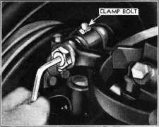
Fig. 23—Turning Pivot Pin to Set Caster and
Camber
tive direction, depending on the
location of the eccentric on the pivot
pin.
After
making a slight turn of the pivot pin, both caster and camber must be rechecked and
adjustments made that will
bring both angles within the
limits given above.
5. After
completing the adjustment, tighten the knuckle support clamp bolt and install the
lubrication
fitting.
KINGPIN INCLINATION
On cars
that have been involved in a collision and camber adjustment does not come within
limits, the kingpin
inclination should be checked. To check the kingpin inclination, remove the
hub |
|||
|
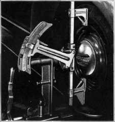
Fig. 22—Position of Contact Bar for Checking
Comber
engage the
tire; then look at the pointer on the camber scale which will indicate the
degree of camber. Make a note of the
camber readings of each wheel.
The camber angle at CURB WEIGHT is1/4 degree negative plus or minus
1/2 degree.
SETTING CASTER AND CAMBER
The caster
and camber adjustments are both performed by turning the upper control arm
pivot pin. This pivot pin is
threaded in the knuckle support and also in the front and rear
bushings in the control arms. In
addition it has a 3/32/' eccentric. Turning the pivot pin affects both
caster and camber—1/2
turn of the pivot pin will change the caster angle 0° 39', while 1/2 turn of the
pivot pin will change the camber angle from 0° to 1° 2', depending on the location of the eccentric
when starting to make
adjustments. Therefore, caster and camber adjustments should be
made together and in relation to each
other.
1. Loosen clamp bolt at upper end of steering
knuckle support, Fig.
23.
2. Remove lubrication fitting from the upper
front pivot pin
bushing.
3. Insert 1/4" Allen set screw wrench through
the hole from which the
lubrication fitting was remove. Fig. 23.
4. Turning the pivot pin in a clockwise
direction increases caster
while turning it in a counterclockwise direction decreases caster. At the
same time the camber may
remain practically the same or
it may move in a positive or nega- |
|||
 |
|||
|
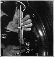
Fig. 24 —Installing Kingpin Inclination
Gauge |
|||
|
|
|||