1942 - 1947 CHEVROLET SHOP MANUAL
Section 3 - Front Suspension, Axle & Springs
|
|
|||
|
3-11 |
|||
|
|
|||
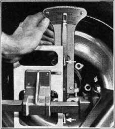 |
leveling
plate against the pins on the indicator as shown in Fig. 25. This puts the indicator
pointer in a vertical position. With the pointer in this position, move the indicator scale forward
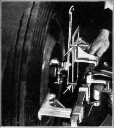
or backward until it reads "0." Then remove the leveling plate. Now, set the wheel in 20 degrees,
place the leveling plate on
the other side of the horizontal bar and slide it slowly along the bar until
its edge contacts both pins on the indicator, Fig. 26. When this is
done the kingpin inclination may be read directly from the Kingpin
Inclination Scale on the indicator.
The correct kingpin inclination should be 4-3/4 degrees plus or minus 1/2
degree.
The kingpin
inclination of the other wheel may be
checked by repeating the operations described above.
When making
the foregoing checks, if the camber check shows the camber to be incorrect
and the kingpin inclination
check shows the kingpin inclination to be correct, this means that
the steering knuckle is bent and must be replaced. On the other
hand, if the kingpin inclination is incorrect, the knuckle support
must be replaced. Naturally,
after replacing a knuckle support it will be necessary to re-adjust both caster and
camber.
TOE-IN
Raise the
car with a jack and place the chalk mark which indicates the point of mean
run-out of the tires in the
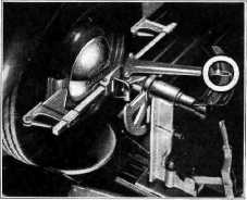
horizontal position; then lower the car on the turntables. Set one
wheel so that when it is contacted by
the contact bars the pointer
will indicate "0" on the Toe-In Scale. Fig. 27. Then go to the other side of the car
and contact the tire with the
contact bars. Then read the amount of toe-in on the Toe-In Scale which
should
A". |
||
|
Fig. 25—Installing Kingpin Inclination Leveling
Plate
Caps and install the Kingpin
Inclination Gauge
on the
spindle, as shown in Fig. 24. Tighten the clamp screws evenly and securely so that the
dial plate can be moved backward and forward for adjustment without moving the clamp on the
spindle nut. Turn the wheel
outward 20 degrees and with the
contact bar in the horizontal position, install the leveling plate on the bar.
Bring the |
|||
 |
|||
 |
|||
|
|
|||
|
Fig. 26-Positioning Levelling Plate With Wheels Set IN 20degs. |
Fig. 27—Setting Contact Bars to Check
Toe-In |
||
|
|
|||