1942 - 1947 CHEVROLET SHOP MANUAL
Section 4 - Rear Axle, Universal Joints & Springs
|
|
|||
|
4-25 |
|||
|
|
|||
|
tion in most sections, there are
some sections where extremely low
temperatures are encountered during the winter months. In such
sections it is advisable to add
10% to 20% kerosene.
During the summer months in
sections where the temperature is
very high and the truck is subject to severe service conditions, a heavier
grade of lubricant such as
S.A.E. 140 may be used.
It is not
necessary to change the lubricant with the seasonal changes, however, it is
recommended that the housing
be drained, flushed, and refilled twice a year, or approximately every 6,000
to 10,000
miles.
SHIFTER MECHANISM AND
ADJUSTMENTS
The shifter
lever on the rear axle is controlled by a hand lever in the cab of the truck and
is connected by rod and
cable linkage to the shifter lever at the rear axle.
The
installation of the control linkage on the various trucks varies somewhat due to the
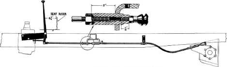
difference in Wheelbase. However, the adjustments are the same on all units. Fig. 51 illustrates
the installation.
Adjustments
1. Check all brackets and U-bolts on the frame
to make sure they are in their
proper position. The brackets
are staked and the cable housings are grooved for the
U-bolts.
2. Shift the shifting lever on the axle
differential carrier to the
fully forward position (low ratio). Disconnect the cable clevis from the
shifting
lever.
3. Disconnect the front adjustable pull rod at
the front end clevis.
4. Loosen the check nut at the back end of the
sleeve passing through the
front support bracket. Unscrew
the sleeve and front adjustable pull rod assembly from the front end
of the second pull rod, just ahead of the rubber boot. |
5. Using a scale on the threaded section at
the front end of the second pull rod, adjust the check nut to allow exactly 11/16" of this
threaded section to extend
forward of the nut —measuring
from the front flat surface of the nut to the front end of the rod, Fig.
51.
6. Loosen the check nut where the rear end of
the front adjustable pull rod
joins the sleeve. Screw the sleeve and front pull rod assembly
back onto the front end of the
rear pull rod. being careful
not to turn the rear pull rod check nut or upset the 11/16" measurement.
Lock sleeve onto front end of
rear pull rod by tightening check nut.
7. Set the shift lever in the cab so that it
is 6-3/4" from the rear
edge of the lever to the front of the seat riser as shown in Fig.
51.
8. Adjust the sleeve in the front support
bracket so that it extends 2"
forward of the support-measuring from the front face of the support to the
front end of the sleeve. While holding the sleeve in this measured
position, and the front pull
rod check nut loose, adjust the pull rod as necessary, by screwing it in or out
of the sleeve, until the front
end clevis pin hole lines up
with the hole in the bottom of the shift lever to allow installation of the
pin— the shift lever in the
cab during this adjustment must be set as outlined in paragraph
7. Insert pin and tighten check nut at front end of
sleeve.
9. At the shift lever on the differential
carrier, make sure the lever is
still in the fully forward position—low ratio, and detent ball seated.
Then adjust the clevis at the
cable end so the hole in the
clevis lines up with the hole in the lever. Insert pin and tighten check
nut.
10. Shift
the hand lever forward and check to
make sure
that the lever on the differential
case is in
the full rear position or high ratio,
with the
ball in the detent.
The cable linkage is lubricated
at the lubrication
fittings
in the connectors. |
||
|
|
|||
 |
|||
|
|
|||
|
Fig. 51—Two-Speed Rear Axle Shifter
Mechanism |
|||
|
|
|||