1942 - 1947 CHEVROLET SHOP MANUAL
Section 4 - Rear Axle, Universal Joints & Springs
|
|
|||
|
4-28 |
|||
|
|
|||
 |
Reassemble
the front universal joint and then bolt the intermediate support bracket to the
frame cross
member.
Assemble
the rear propeller shaft and adjust the packing retainer on the rear sleeve
yoke of the intermediate
universal joint.
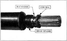
NOTE—When necessary to replace
a cork oil seal in this retainer, press the old one out of the retainer,
and, because it is split, Fig. 58, it can then be removed from the
propeller shaft. |
||
 |
|||
|
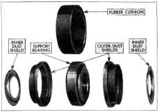
Fig. 56—Layout of
Intermediate Support Bearing Parts
2. Place one of the inner dust shields on the
shaft with the offset in the
shield away from the bearing,
as shown in Fig. 56. Drive the bearing on the shaft, using the universal
joint yoke as a driver. Then
install the other inner dust shield on the shaft with the offset away from the
bearing.
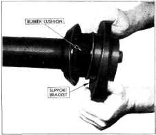
3. Install the rubber cushion over the
bearing, as shown in Fig.
54.
4. Coat the outside surface of the rubber
cushion lightly with soft soap
and slide the support bracket
over the rubber cushion as in Fig. 57.
5. Install the front yoke of the intermediate
universal joint, making
sure that the yoke is turned 90 degrees, in relation to the rear yoke of
the front universal joint,
which is a part of the propeller shaft. Then, by installing the rear
yoke of the intermediate
universal onto the rear propeller shaft so that it is in the same plane
(line) with the front yoke of
the rear propeller shaft rear
universal joint, it will correctly align all three universal
joints. |
|||
|
Fig 58— Packing at Intermediate Joint Rear Yoke
8.
Lubricate the universal joints with S.A.E. 90 gear lubricant (transmission
lubricant).
FRONT PROPELLER SHAFT ASSEMBLY
3/4-TON AND 3/4-TON SPECIAL TRUCKS
The front propeller shaft assembly
on the 3/4-ton and 3/4-ton special
truck differs from the 1-1/2-ton models in that it is of the enclosed type,
and has a bushing type front
universal joint, Fig. 59.
The
housing incorporates the universal ball as part of the assembly. A thin wall bushing
is pressed into the front end
of the housing tube. The hub of the rear yoke of the front universal joint
takes its bearing in this
bushing. The rear end of the shaft is supported by a single row ball bearing
of the permanently lubricated
and sealed type. A spring loaded oil seal is pressed into the housing
ahead of the bearing and a
dust shield is assembled on the shaft at the rear of the
bearing.
A rubber
cushion slips over the machined rear end of the housing. This cushion, in turn,
fits inside the sleeve which is
a part of the support bracket.
Removal from Truck
1. Split the intermediate universal joint by
removing the two trunnion
bearing "U" clamps from the front yoke of the universal. Tape the
bearings as already
described and drop the front end of the rear propeller
shaft.
2. Remove the four bolts which attach the
universal ball retainer to
the rear end of the transmission and slip the retainer back on the
tube. |
|||
 |
|||
|
Fig. 57—Installing Bearing Support
Bracket |
|||
|
|
|||