1942 - 1947 CHEVROLET SHOP MANUAL
Section 6 - Engine
|
|
||||
|
6-22 |
||||
|
|
||||
|
tion. Bend pipe on right side of
block to clear the push rod cover. Then bend the upper portion of pipe to pass through the hole in the
cylinder head. Connect the pipe to the valve rocker shaft coupling.
Fill the cooling system with water, start the engine and check all
connections for both oil and water leaks.
CYLINDER HEAD ASSEMBLY
One of the most important units of
any valve-in-head engine is the cylinder head. It contains not only the
combustion chambers and spark plugs but the valves, inlets ports, exhaust
ports and the necessary water passages to maintain the proper temperature
of these important parts.
The Chevrolet cylinder head is
designed to give a compression ratio of 6.50 to 1 and 90 horsepower (the
same head giving 6.62 to 1 ratio and 93 horsepower on the heavy duty
235.5 cubic inch engine.)
The combustion chamber is designed
for use with a flat top piston that provides exceptionally compact
combustion volume on the exhaust valve side where the spark plug is
located.
On the intake valve side the head
is machined so that, except for a shallow recess in which the intake valve
is located, the bottom face of the head over the piston is flat and is
separated from the piston at top dead center by the thickness of the
cylinder head gasket only.
The valves are so located that
they permit the incoming charge of fuel mixture to enter the combustion chamber, do its work, and leave the
chamber after its work is done, without restriction, making use of
the volume of mixture efficiently with the least possible
disturbance.
This type
cylinder |
VALVES
Chevrolet valves have a high
resistance to heat, corrosion and pitting. They are made from sili-chrome
stainless steel by what is known as an extruding process. This
manufacturing process is a development of Chevrolet and it shapes the
rough valve in one operation.
From the rough forging to the
finished product all operations are carefully performed and
inspections are frequent.
The end of the valve stems are
hardened electrically to reduce wear at the contact point with the
rocker arm.
Valve Guides
The clearance between the valve
guides and the valve stems is very important. Lack of power and noisy
valves, in many instances, can be traced to worn valve
guides.
The intake valve guides should be
checked with a new intake valve and the exhaust guides with a new exhaust
valve, because the diameters of the stems are different on these
parts.
The exhaust valve guide is
designed to bring the inner end of the guide flush with the inside of the
valve port. With this design the heat dissipating properties are increased
and aids in eliminating sticking valves. |
|||
 |
||||
|
head is the
result of many years' experience
in providing ample
water space around the
valves and spark plugs in
addition to a means for most
effective distribution of
water. The coldest water is
taken |
 |
|||
|
into the cylinder head and
directed toward the |
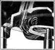
Fig. 46—Cylinder Head Water
Nozzles |
|||
|
valve seats by means of
•
eight small copper nozzles pressed
into the lower part of the head. There are three kinds of these nozzles
used—long and short type, each with a single opening used to direct single
streams of water to the single exhaust valves at the end cylinders
and another with two openings which direct two streams of water to the
other exhaust valves, Fig. 46. |
||||
|
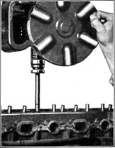
Fig. 47—Removing Valve Guide |
||||
|
|
||||